Introduction to Python and Microcontrollers
Joystick
Read a 2-axis analog joystick’s X position, Y position, and button press, and print all three to the Shell.
New Concepts
- Joystick
Joystick
A joystick module is really two rotary potentiometers mounted at 90° to each other, plus a push button underneath, all on one PCB.
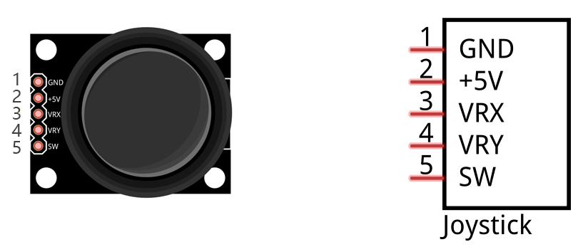
| Pin | Function |
|---|---|
| GND | Ground |
| +5V | Power |
| VRX | X-axis analog output |
| VRY | Y-axis analog output |
| SW | Push-button digital output (Z axis) |
Moving the stick along the X or Y axis turns one of the internal potentiometers, producing an analog voltage on VRX or VRY — so reading position requires the ADC, just like Read the Voltage of a Potentiometer. Pressing the stick down (the Z axis) closes a simple switch, which is a digital signal — read with a plain GPIO pin, the same as a push button.
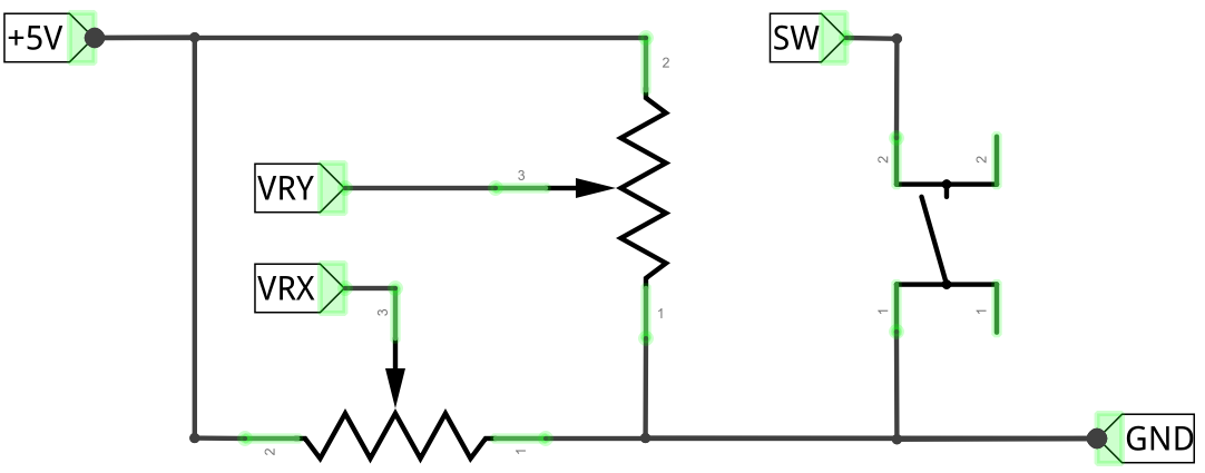
Component List
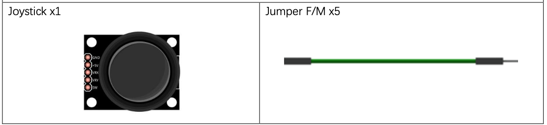
Circuit
Wiring Diagram
Disconnect all power before building the circuit. Reconnect once verified.
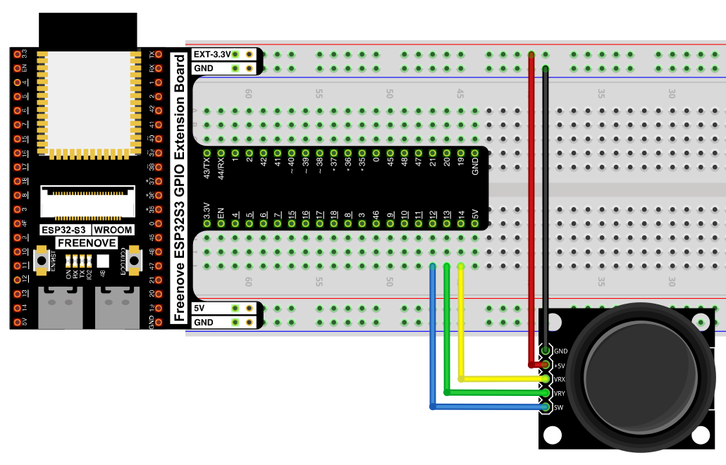
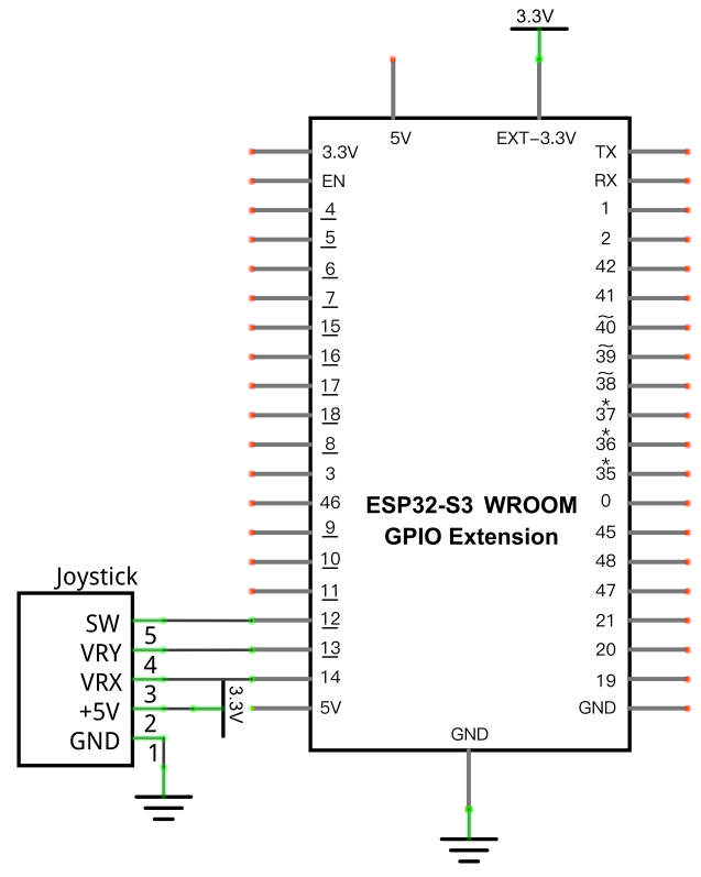
Connections:
- Joystick GND → GND
- Joystick +5V → 5V
- Joystick VRX → GPIO14
- Joystick VRY → GPIO13
- Joystick SW → GPIO12
Schematic Diagram
Code
File: 03_sensors/code/Joystick.py
from machine import ADC,Pin
import time

xVal=ADC(Pin(14))
yVal=ADC(Pin(13))
zVal=Pin(12,Pin.IN,Pin.PULL_UP)

xVal.atten(ADC.ATTN_11DB)
yVal.atten(ADC.ATTN_11DB)
xVal.width(ADC.WIDTH_12BIT)
yVal.width(ADC.WIDTH_12BIT)

try:
    while True:
      print("X,Y,Z:",xVal.read(),",",yVal.read(),",",zVal.value())
      time.sleep(1)
except:
    xVal.deinit()
    yVal.deinit()
How to Run
Online
- Open Thonny →
03_sensors/code/. - Double-click
Joystick.py. - Click Run current script. Move the stick or press it down — the printed X, Y, Z values in the Shell change.
Code Explanation
Set up two ADC inputs and one digital input
xVal=ADC(Pin(14))
yVal=ADC(Pin(13))
zVal=Pin(12,Pin.IN,Pin.PULL_UP)
X and Y are analog (ADC), since they come from potentiometers. Z is a plain digital input with the internal pull-up enabled, since it’s just a button — pressing it pulls GPIO12 LOW, same logic as Button & LED.
Read and print all three axes
print("X,Y,Z:",xVal.read(),",",yVal.read(),",",zVal.value())
xVal.read() and yVal.read() return 0–4095 ADC values; zVal.value() returns 0 (pressed) or 1 (released).
Key Concepts
- Mixed analog/digital sensing: one module can combine ADC and GPIO inputs — read each according to its own signal type
- Potentiometer-based joysticks: the X/Y axes work exactly like the rotary potentiometer from Chapter 9, just packaged two-at-once
See Class ADC for the full API reference.
Further Exploration
- Map the raw 0–4095 X/Y values to a -100 to 100 range centered on the joystick’s resting position.
- Use the Z button press to reset a counter or toggle a mode.
Adapted from Python_Tutorial.pdf Project 13.1