Introduction to Python and Microcontrollers
Blink (External LED)
Blink an external LED wired to the ESP32-S3 via a breadboard. This introduces basic circuit concepts: LEDs, resistors, and breadboards.
New Concepts
- LED
- Resistor
- Breadboard
LED
An LED is a diode that emits light when current flows through it. It is polar — current must flow in the correct direction:
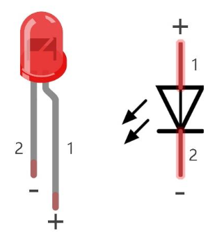
- Longer pin = positive (anode) → connect to GPIO / power
- Shorter pin = negative (cathode) → connect to GND
Warning: Never connect an LED directly to power without a resistor. Operating voltage range: 1.9V–3.4V. Exceeding this will burn out the LED.
Resistor
Resistors limit current flow, protecting the LED. Resistance is measured in Ohms (Ω). Value is indicated by coloured bands on the body.
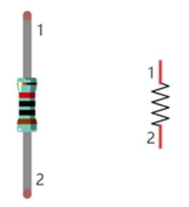
Ohm’s Law: I = V / R
- Example: 5V supply, 10kΩ resistor → I = 5V / 10,000Ω = 0.5mA
Resistors are non-polar — direction doesn’t matter.
For more details on resistors see Resistors reference doc
Breadboard
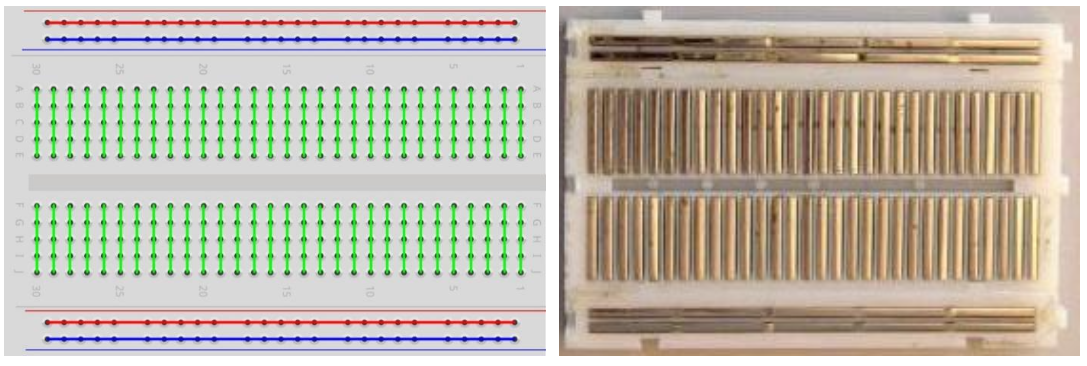
Rows of holes on a breadboard are electrically connected internally. Insert components into the same row to connect them without soldering. Power rails (marked + and −) run along the sides. The ESP32 micro controller is plugged into a breadboard.
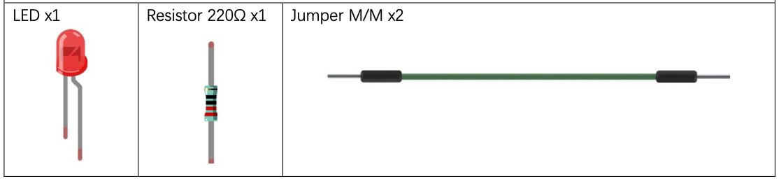
Component List
Circuit
Wiring Instructions:
- ESP32-S3 GPIO2 → 220Ω resistor → LED anode (longer pin)
- LED cathode (shorter pin) → GND
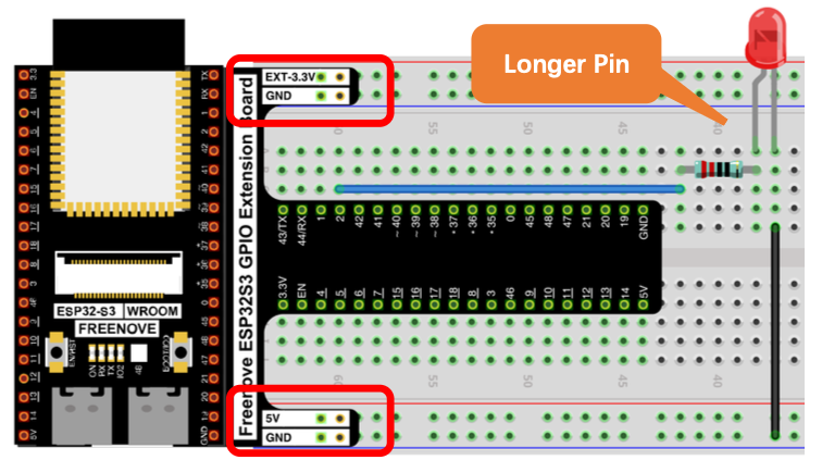
Wiring notes:
- Connect the longer pin (anode) of the LED toward the resistor/GPIO side.
- Disconnect all power before building the circuit, then reconnect once verified.
Caution: Avoid short circuits — never connect 5V or 3.3V directly to GND.
Code
File: ./Blink.py
from time import sleep_ms
from machine import Pin

led = Pin(2, Pin.OUT)  # create LED object from pin2, Set Pin2 to output

try:
    while True:
        led.value(1)    # Set led turn on
        sleep_ms(1000)
        led.value(0)    # Set led turn off
        sleep_ms(1000)
except:
    pass
The code is the same as before, GPIO2 controls both the built-in LED and the external LED wired in this circuit.
How to Run
Online (while connected to PC)
- Open Thonny and navigate to
01_first_examples/code. - Double-click
Blink.py. - Click Stop/Restart backend, wait for connection.
- Click Run current script — the external LED starts blinking.
Further Exploration
Circuits can be represented with a wiring diagram like we saw above or a schematic diagram. A wiring diagram shows how the circuit is connected in the real world, the schematic diagram shows how it is electrically connected.
Here is a schematic for this circuit
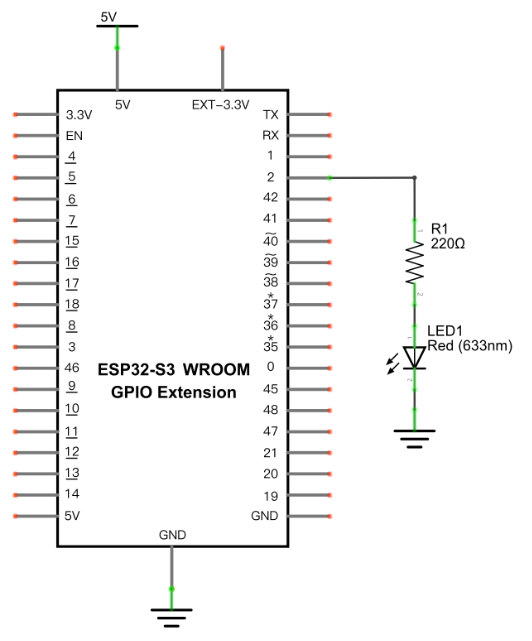
Adapted from Python_Tutorial.pdf Project 1.2